An Introduction to the 56K V.90 Software Modem
By Frank Gao, Ph.D
GAO Research Inc.
The V.90 modem is the latest technology to offer faster Internet connection speeds without requiring that consumers subscribe to more expensive digital line services. Before V.90 technology, modems were theoretically limited to about 35 Kbps by the quantization noise that affects analog to digital conversions (the practical limit was actually 33.6 Kbps). However, in today's world of increasing digital transmission facilities it is safe to assume that an increasing number of Internet service providers (ISPs) are digitally connected both to the Internet and to a telephone company's central office (CO). When this is the case, there is a clear digital connection downstream from the ISP's modem to the CO's line card that serves the user and contains a digital to analog converter. The result of having this digital connection is that an analog to digital conversion (and therefore quantization noise) is avoided between ISP and CO. Without the limits imposed by quantization noise, it is theoretically possible to achieve downstream connection speeds of up to 64 Kbps. Practically, however, this is not yet possible. Performance barriers such as µ-law quantization reduce the effective data rate of V.90 modems to a maximum of 56 Kbps downstream.
In the downstream direction, the V.90 modem operates using pulse amplitude modulation (PAM). The downstream signal consists of 8,000 symbols per second and each symbol is maximally coded from 7 bits of each 8 bit pulse code modulation (PCM) word. This translates into 128 possible amplitude levels in the PAM signal. Because most users are not digitally connected to the CO, an analog to digital conversion and the associated quantization noise cannot be avoided in the upstream direction. This means that V.34 modulation techniques must be used and upstream speeds are still limited to 33.6 Kbps. Figures 1 and 2 illustrate the basic configuration of V.90 server and client modems (downstream direction) as specified by the International Telecommunications Union (ITU) V.90 standard.
Since the V.90 standard was just completed in late September 1998, this article provides a timely overview of the V.90 modem standard, transmitter and receiver functions, barriers to performance, and software implementation. This overview should help designers make educated decisions about designing products with V.90 modem fuctions.
The Standard
Making any kind of decision about 56K PCM modems was difficult at the beginning of 1997 when major modem manufacturers such as Lucent, Rockwell, and US Robotics started marketing two different 56K modem technologies. For almost a year, there was a great deal of uncertainty about 56K modems due to the incompatibility of these two technologies and the lack of a standard. Finally, in February 1998, the draft of the ITU V.90 standard was released and it resolved the compatibility issues. The final version was ratified in late September 1998 with only a few minor editorial changes from the draft. All major modem manufacturers have now announced that their products comply with the new standard. With the implementation of the standard, any V.90 client modem can connect with any central-site modem that supports the standard.
The ratified V.90 standard defines the principal characteristics of the 56K modem as follows:
-
Duplex mode of operation over the public switched telephone network (PSTN) and switched digital networks
Use of echo cancellation techniques for channel separation
PCM modulation downstream at a symbol rate of 8 k and V.34 modulation upstream
Synchronous channel data signaling rates downstream from 28 Kbps to 56 Kbps in increments of 1.3 Kbps and upstream from 4.8 Kbps to 33.6 Kbps in increments of 2.4 Kbps
The modems utilize adaptive techniques to achieve as close as possible to the maximum data signaling rates supported by the channel on each connection
If a connection does not support V.90 the modem falls back to full duplex V.34 operation
During modem start-up, the data signaling rate is established by the exchange of rate sequences
V.32bis automode procedures and Group 3 facsimile machines support Automoding to V.Series modems
V.8 and, optionally, V.8bis procedures are utilized during modem start-up or selection
Transmitter
The major functions of the V.90 modem transmitter (server side) are illustrated in Figure 1 and described in more detail below.
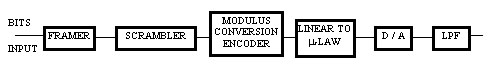
Figure 1: Digital Modem Transmitter (Server Side)
Scrambler
As in V.34 modems, the scrambler randomizes the binary input data to spread the transmit signal spectrum over the transmit band.
Encoder
The encoder consists of a modulus conversion encoder (with convolutional spectral shaping) and uses the scrambled binary input data to generate digital output symbols. In V.34 modems, the binary data
are mapped into 2-dimensional QAM signal points, while in V.90 modems the signal constellation points are chosen from the (-law quantization levels. This is a key difference between V.90 and V.34
modems and makes the mapping procedure for V.90 quite different from the mapping procedure for V.34.
Mapping
According to the ITU G.711coding standard, the (-law quantizer has 255 non-uniformly spaced output levels, including 127 positive and 127 negative levels and a level at zero. These levels are
symmetric around zero and divided into 16 segments: (1, (2,..., (8. Segments +1 and -1 contain 15 levels, with a uniform spacing of two. Level zero is shared by both segments. All other segments have
16 levels and each one has twice the spacing of the previous segment. A two-step-mapping algorithm maps binary data into the (-law signal space described above. By minimizing the possibility of using
the signal points with the smallest distance, the algorithm minimizes the error rate while keeping the memory and complexity requirement at a level similar to the V.34 mapping algorithm. Note that
the use of a sequence that utilizes all 255 levels equiprobably is not allowable because its average energy exceeds regulatory constraints.
Trellis Coding
Because of the low constellation expansion, 4D trellis codes can be applied to the V.90 modem and such use can increase the minimum distance between allowable sequences. The output digital symbols of
the encoder are sent to the (-law D/A and converted into analog signals for transmission.
Receiver
The main functional blocks of the receiver are illustrated in Figure 2, and some are described in more detail below.
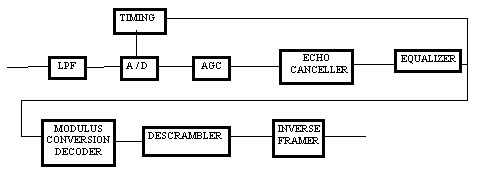
Figure 2: Analog Modem Receiver (Client Side)
One of the receiver's main tasks is to perform the inverse of the transmitter functions such as the modulus conversion decoder, descrambler, and inverse framer. The receiver also carries out the following operations to offset channel impairments.
Equalization
The samples received by the modem sustain deterioration from intersymbol interference (ISI). The ISI results from the linear amplitude and phase dispersion in the channel, which broadens the
transmitted symbols and causes them to interfere with one another. In order to increase the transmission performance, a filter is required to model the estimated inverse transfer function of the
channel and thus perform channel equalization. Typically, a linear adaptive transversal filter is used and its coefficients are adjusted by the Least Mean Square (LMS) algorithm.
Timing Recovery
Timing recovery procedures are used to recover a clock at the symbol rate, or a multiple of the symbol rate, from the modulated waveform. This clock converts the received continuous-time signal into
a discrete time sequence of data symbols. The need for timing recovery imposes additional requirements on the modulation technique, which are not required when a separate clock is available. The
recovery of the timing information in a signal is affected by the statistics of the signal, the line code, and the pulse shape.
Automatic Gain Control
The automatic gain control operates over a wide dynamic range and maintains the output signal at a constant level.
Echo Cancellation
The hybrids in a telephone system cause echoes. These echoes are harmful to data transmission over telephone networks. Echo cancellers use the received and delayed transmitted signals to estimate the
echoes. Echo cancellation is achieved by subtracting the estimated echo signals from the received signals. The echo canceller must be trained before effective echo cancellation is achieved. Adaptive
algorithms are one of the methods used for training the echo cancellers. The LMS (Least Mean Square) algorithm is the most widely used for this task because of its computational efficiency.
Barriers to Performance
The design of a V.90 modem must not only comply with the standard as outlined above; it must also address the various impairments found in the PSTN and any regulatory constraints. The following are some of the barriers to achieving maximum data rates with a V.90 modem.
-
Analog: loaded loops, bridged taps, code conversions, D/A nonlinearities, intermodulation distortion, talker echo, analog pad loss, and loop noise. Also, the (-law levels selected for the PCM
modem signal constellation are limited by the FCC energy constraint (-12dBm/3sec).
Digital: adaptive differential PCM, robbed-bit signaling, PCM link conversions, and digital pad loss.
Additional A/D and D/A conversions can occur when there are analog switches or analog trunk sections in the network. They can also occur with digital loop carrier systems. These conversions may
cause V.90 modems to fallback to V.34 data rates.
Software Implementation
The performance barriers and functional blocks described above are necessary considerations, but on a higher level, implementation issues must also be taken into account. OEMs need to get their products to market quickly. They must also make sure these products are upgradable to any new versions of the ITU V.90 standard that may be released. Hardware implementations of V.90 modems will be much more difficult to upgrade than software implementations. A software implementation on a DSP is not only upgradable; it also allows multiple functions to run on one processor. This gives the designer flexibility in product design as well as a better cost/performance ratio. Once the decision is made to go with a software implementation, OEMs must either design that software in-house or license it. Modem software is complex and therefore difficult to develop. It requires a great deal of time to create high performing modem software and time to market is critical in the modem industry. If a product is released too late, it will miss a narrow window of market opportunity. Fortunately, there are software vendors such as GAO Research & Consulting Ltd. that have quality modem code ready for licensing. This makes licensing software from a vendor the fastest and most economical option for OEMs developing products with V.90 modems.
Due to the above reasons, interest in software implementations of V.90, as well as other modem and fax data pumps for DSPs and microprocessors, has increased dramatically in recent years. With the increasing popularity of software implementations of modem and fax technology, designers need to understand the operational principles and software building blocks of modems and faxes in order to make educated decisions about licensing this software.
Characteristics to look for if you are licensing V.90 software:
-
It must comply with the ITU V.90 standard.
The software must be tested according to the standard.
It must take up the smallest possible amount of memory and MIPS.
The vendor must have a good reputation for quality.
The vendor must provide good support because the software is highly complex and hardware dependant.
Summary
This article has outlined the operational principles and software building blocks of modems in order to give designers the information they need to make an educated decision about how to implement a V.90 modem. The V.90 modem is an innovative technical advance, which extends analog capabilities to increase speed for Internet applications. This new modem technology makes use of advanced encoding and mapping techniques, but there are still many performance barriers V.90 modem designers must overcome in order to provide data rates close to 56 Kbps. As with other pre-standard modem implementations, there were serious compatibility issues between competing technologies, but these have been resolved by the V.90 standard. Because the standard is so new, V.90 modems must be able to upgrade to new versions. The best way to ensure easy upgrades is to implement a software-based modem rather than a hardware chipset-based modem. Furthermore, software-based modems offer faster time to market and better cost-performance ratios in most applications.
Reprinted here with permission of TechOnLine
About the Author
Dr. Frank Gao is the founder and President of GAO Research Inc., a leading supplier of software modem, fax, speech, and telephony technologies. Dr. GAO received his Ph.D. degree from the University of Toronto and was employed by Bell Northern Research Ltd. before founding GAO. Dr. Gao can be reached at: frankgao@gaoresearch.com.