Modem and Fax Standards and Software |
||||||||||||||||||||||||||||||||||||||||||||||||||||||||||||||||||||||||||||||||||||||||
|
By Frank Gao, Ph.D Introduction For more than a decade, the global demands for voice and data communications have been growing at a phenomenal rate. With the explosion of the World Wide Web and Internet communications, there are strong demands for reliable communication over the last-mile to the home at low-cost and high-speed. As a result, interest in modem and fax technologies, particularly modem and fax software, has increased substantially. This article summarizes the commonly used standards for modem and fax and presents a tutorial on the principles of modem operation. The software for V.34 modem (with all fallbacks) from GAO Research & Consulting Ltd. (GAO) is presented as an example. Modem And Fax Standards Since the release of the V.21 International Telecommunications Union modem standard more than 15 years ago, various modem and fax modulation standards have been developed and released. In this article, we will present an overview of these standards and discuss the latest ones in more detail. 1, Modem Standards Modem technologies are specified by a group of International Telecommunications Union (ITU) standards for use on general switched telephone networks (GSTNs) and point-to-point 2-wire leased circuits. The most commonly used standards are summarized in Table I. The data rates of the modems specified by the standards vary from 300bps (V.21) to 33.6 kbps (V.34) and recently 56 kbps (V.90). There are two commonly used protocol standards that commercial modems require: V.42bis for data compression and V.42 for error correction. A typical commercial modem incorporates all of the V series modem standards listed in Table I, as well as V.42 and V.42bis.
2, DSL Modems In a further attempt to improve access technologies, ADSL is now being used to offer higher bit rates over the copper pair. The ADSL modem offers extremely high bit rates of up to 8 Mbps downstream and 640 kbps upstream for Internet applications through the data channel and provides a POTS channel for either a telephone or a V-series modem. Tests at many telephone companies have proved that ADSL technology is practical and many North American telephone companies have already rolled out commercial services. As consumers continue to demand higher capacity access technologies for Internet applications and ADSL technology matures and becomes more ubiquitous, the ADSL modem will become the driving force of the modem market. In a further attempt to improve access technologies, ADSL is now being used to offer higher bit rates over the copper pair. The ADSL modem offers extremely high bit rates of up to 8 Mbps downstream and 640 kbps upstream for Internet applications through the data channel and provides a POTS channel for either a telephone or a V-series modem. Tests at many telephone companies have proved that ADSL technology is practical and many North American telephone companies have already rolled out commercial services. As consumers continue to demand higher capacity access technologies for Internet applications and ADSL technology matures and becomes more ubiquitous, the ADSL modem will become the driving force of the modem market. ADSL Lite (commonly called G.Lite after the developing ITU standard) is slower than full-rate ADSL. G.Lite technology enables up to 1.5 Mbps downstream and 500 kbps upstream while still providing a POTS channel. Although this is not as fast as ADSL, it is still a huge leap forward from V.90 or ISDN. G.Lite does have a major advantage over ADSL � no splitter. The G.Lite modem will simply be plugged into the phone jack. This means no installation visit from the telephone company, which reduces costs. Table 2: DSL Services and Rates
The American National Standards Institute (ANSI) approved Issue 1 of their ADSL DMT standard (T1.413) with an annex contributed by the European Technical Standards Institute (ETSI) in 1995. The latest version of the ANSI T1.413 ADSL standard is Issue 2 (1998). The main changes from T1.413 Issue 1 to Issue 2 are as follows:
The International Telecommunications Union (ITU) is now working toward a G.dmt standard for ADSL which is modeled after ANSI T1.413 Issue 2 and ETSI Technical Report 328. A G.lite standard from the ITU is also on the way and the G.991.1 (HDSL) standard has already reached technical completion. 3, V.90 Modem With increasing numbers of Internet web sites offering complex graphical content, users have been facing growing delays in the downloading process. With the introduction of V.90 modem technology, personal computer users can achieve Internet connections at speeds of up to 56 kbps for downloading graphics and/or for supporting videoconferencing or collaborative computing applications. The V.90 technology takes advantage of the fact that digital transmission facilities have been rapidly replacing analog transmission facilities on the Public Switched Telephone Network (PSTN). It is assumed that an Internet service provider (ISP) is digitally connected both to the Internet and to a telephone company�s central office (CO) via a server modem. This means that a conversion from digital to analog lines in the connection from ISP to CO is avoided. The downstream connection is extended from the CO to the user via a line card with a digital to analogue converter (DAC), providing a pulse amplitude modulation (PAM) analog signal to the client modem. The downstream signal consists of 8 thousand symbols per second with each symbol maximally coded from 7 bits of each 8 bit pulse code modulation (PCM) word. This translates into 128 possible amplitude levels in the PAM signal. Data rates of up to 56 kbps are the result. For the upstream connection, the user's analog signal is extended to an ISP via a CO line card A/D converter. The current version of the V.90 standard supports data rates of up to 33.6 kbps. Future versions of V.90 may push the upstream data rates higher. 4, Fax Standards Fax technologies are also specified by a group of ITU standards. The standards vary from 4,800bps (V.27ter) to 14,400bps (V.17), and 33,600bps (V.34). The most commonly used standards are summarized in Table 3. Table 3: ITU Fax Standards
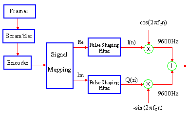
Modem And Fax Principles Modem and fax capabilities have traditionally been implemented using dedicated chipsets, which are offered as off-the-shelf black boxes. Engineers who use these black boxes in their designs often do not need to understand their internal operational mechanisms. With the increasing popularity of the software implementation of modem and fax, designers need to understand these operational principles and software building blocks. The modem or fax software is composed of two parts: the protocols and the data pump. The protocols are not computationally intensive and are therefore typically handled by a microcontroller. The data pump is the core of the modem and fax. The major components of a data pump include the modulator, demodulator, encoder, decoder, scrambler, descrambler, equalizer, echo canceller, timing recovery, and carrier recovery. Figures 1 and 2 illustrate the signal processing functions of the V.34 modem. The V.34 data pump algorithms can be categorized into three groups: handshaking, transmitter, and receiver. 1, V.34 Handshaking The V.34 modem handshaking is composed of four phases:
2, Transmitter The transmitter (Figure 1) uses the structure specified by the ITU V.34 standard. Two important parts of the transmitter are the scrambler and the encoder. The purpose of the scrambler is to facilitate effective transmission of data over the telephone channel and to improve the convergence of the adaptive equalization and echo cancellation in the receiver. The scrambler randomizes the input binary data to spread the transmit signal spectrum over the transmit band. The encoder consists of a shell mapper, differential encoder, precoder, Trellis encoder and a non-linear encoder. Three new techniques have been employed in the V.34 encoder: multidimensional Trellis coded modulation (MD-TCM), shell mapping, and precoding equalization. The concept behind the MD-TCM is that the coding and modulation are combined so that the modem can benefit from high reliability with a limited transmission frequency bandwidth. The standard recommends three convolutional encoder structures for the transmitter. The three Trellis codes, 16-state rate-2/3, 32-state rate-3/4, and 64-state rate-4/5, all with four-dimensional QAM constellation, can achieve asymptotic coding gains of about 5 dB. Shell mapping reduces the average signal energy and thus improves the modem performance without changing the signal-to-noise ratio (SNR). The precoding technique, which is a nonlinear equalization scheme, can reduce the effects of noise enhancement in the equalizer.
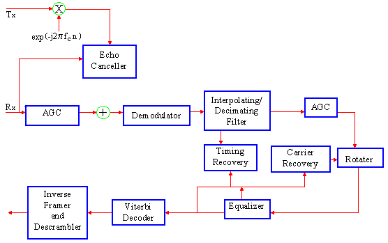
Figure 1 Transmitter of the V.34 Modem Software from GAO 3, Receiver The ITU V.34 standard does not specify the structure of the receiver. This gives modem designers a great deal of flexibility in the receiver implementation. As shown in Figure 2, the receiver is more complicated than the transmitter and several of its functions are the inverse of the transmit functions. The receiver consists of seven major functional blocks: the automatic gain control (AGC), equalizer, timing recovery, carrier recovery, echo canceller, demodulator, and Trellis decoder.
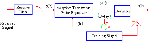
Figure 2 Receiver of the V.34 Modem Software from GAO A) Equalizer The samples received by the modem suffer from intersymbol interference (ISI). The ISI results from the linear amplitude and phase dispersion in the channel, which broadens the transmitted signals and causes them to interfere with one another. In order to increase the transmission performance, a filter is required to estimate the inverse transfer function of the channel and to perform channel equalization. Typically, a linear adaptive transversal filter is used and its coefficients are adjusted by the Least Mean Square (LMS) algorithm, as shown in Figure 3.
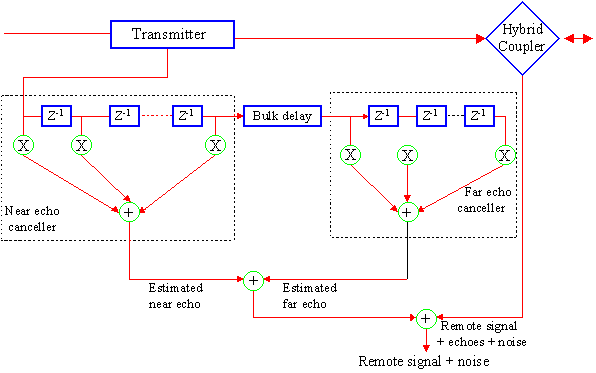
Figure 3 The Equalizer of the V.34 Modem Software from GAO B) Timing Recovery The purpose of timing recovery is to recover a clock at the symbol rate (or a multiple of the symbol rate) from the modulated waveform. This clock allows the received continuous-time signal to be converted into a discrete time sequence of data symbols. The need for timing recovery imposes additional requirements on the modulation technique, which are not present when a separate clock is available. The strength of the timing information in a signal is affected by the statistics of the signal, the line code, and the pulse shape. C) Carrier Recovery In passband systems, the carrier frequency is generated by a timing reference in the transmitter. Coherent demodulation of a passband signal requires exactly the same carrier frequency and phase. If the symbol timing is known, the carrier frequency can be derived. Section 3.3.B shows that symbol timing can be derived without knowledge of the carrier phase. Hence, when a receiver starts receiving data, it should first derive timing using the techniques discussed in section 3.3.B, then estimate the carrier phase, and finally adapt the equalizer. D) Echo Cancellers The hybrids in a telephone system cause near-end and far-end echoes. These echoes are harmful to data transmission over telephone networks. Near-end and far-end cancellers are necessary to cancel the echoes. These echo cancellers use the received and delayed transmitted signals to estimate the echoes. Echo cancellation is achieved by subtracting the estimated echo signals from the received signals, as shown in Figure 4. The echo canceller must be trained before effective echo cancellation is performed, in order to be able to model the echo response precisely. Adaptive algorithms can be used for training the echo cancellers. In practice, the LMS (Least Mean Square) algorithm is the most widely used for this task because of its computational efficiency. The far echo is weaker than the received signal, and is therefore generally easier to cancel than the near echo; however, the far echo may be frequency translated when it passes through frequency converters (modulators and demodulators) on the four-wire circuits. This phenomenon is called a phase roll (or frequency offset of the far echo) and is a non-linear impairment. Non-linear compensation techniques must therefore be used for effective far echo cancellation if a phase roll exists. E) Viterbi Decoder
Figure 4 Echo Canceller of the V.34 Modem Software from GAO The above example of GAO V.34 modem software complies fully with the ITU standards. It incorporates many state-of-the-art algorithms. The principles involved can easily be applied to other modem and fax techniques. Software Implementation Interest in modem and fax software for DSPs, ARM, MIPS, and Pentium processors has increased substantially. This is due to the fact that software modems based on these processors often offer better cost performance ratios than fixed-function modem chip sets. This approach also offers flexibility in bug fixing and functional upgrades, as well as flexibility in designs for different products. A general-purpose programmable processor, such as a DSP or an ARM processor, can be used to replace several dedicated functional chips that are required in a traditional design. All signal processing functions are implemented in the software, which facilitates upgrading either by downloading the software through the host processor or by replacing a ROM containing the software. Developing algorithms and software modules that have both good performance and minimal memory and MIPS requirements is a challenging task. Understanding signal processing functions and their requirements is crucial for the success of a product design which uses modem software. The modem and fax software developed by GAO Research & Consulting Ltd. has been fine-tuned to maximize its performance in both MIPS and memory. The software from GAO covers the V.90 modem standard, the V.34 modem standard, the V.17 fax standard and all their fallback standards. GAO has two versions of it�s modem and fax software in C, one in the floating-point format for Pentiums and other floating-point processors, and another in the fixed-point format for ARM, MIPS and other fixed-point processors. The company also has two versions in assembly language, one for TMS320C54x DSPs and the other for ADSP21xx DSPs. About the Author Dr. Frank Gao is the founder and President of GAO Research Inc., a leading supplier of software modem, fax, speech, and telephony technologies. Dr. GAO received his Ph.D. degree from the University of Toronto and was employed by Bell Northern Research Ltd. before founding GAO. Dr. Gao can be reached at: frankgao@gaoresearch.com. |
||||||||||||||||||||||||||||||||||||||||||||||||||||||||||||||||||||||||||||||||||||||||